
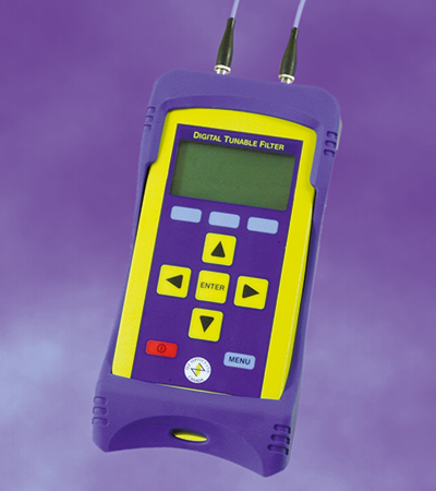
デジタル波長可変フィルター
TF-100
手軽に波長選択
特長
- 狭線幅
- 偏波無依存
- 広波長範囲
- SMF、MMF、PMF対応
- 高分解能 • USBインターフェース
仕様
| 電源 | Universal 110/220 Volt AC/DCアダプタ |
|---|---|
| インターフェース | USB |
| 分解能 | < 0.1 nm(typ.) |
| 再現性 | < 0.2 nm(typ.) |
| チューニングレンジ | 50 nm |
| 波長範囲 | 1520~1570(C-band) 1570~1620(L-band) 1470~1520(S-band) 他波長範囲はオプション |
| 線幅(FWHM) | 1.1 ±0.1 nm(標準)0.3 nm(オプション) |
| 波長温度依存性 | < 0.002 nm/℃(typ.) |
| PDL | < 0.3 dB(typ.) |
| 挿入損失 | < 2.5 dB(typ.) |
| Power Handling | 最大200 mW(標準パッケージ) |
| 応答時間 | 50 nm 可変 < 1秒、1 nm 可変 < 0.1秒 |
| 大きさ | 150 × 81 × 46 mm |
| 重量 | 450 g(保護ブーツ除く) |
| 動作温度 | -10°C ~ 55°C |
| 保存温度 | -30°C ~ 70°C |
| Certifications:CSA-C22.2 NO. 61010-1-12 | Safety requirements for electrical equipment for measurement, control, and laboratory use - Part 1: General requirements - Third Edition; Update No. 1: July 2015; Update No. 2: April 2016 |
| Certifications:UL 61010-1 | UL Standard for Safety Electrical Equipment For Measurement, Control, and Laboratory Use; Part 1: General Requirements - Third Edition; Including Revisions through July 15, 2015 |
| Certifications:CE | Certifies the product meets all EU health, safety and environment requirements including the latest RoHS & REACH compliance, which ensures consumer safety |
用途
- 波長可変光源
- スペクトル解析
- ファイバーデバイスの製品開発
注文方法
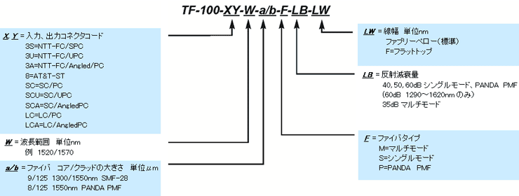
型番の一例
TF-100-3S3S-1520/1570-9/125-S-40-1.2
- シングルモードファイバー:9/125µm
- 波長範囲:1520~1570nm
- 入力コネクタ:FC/SPC
- 出力コネクタ:FC/SPC
- 反射減衰量:40dB
- FWHM:1.2nm(ファブリペロフィルター)
アプリケーションノート
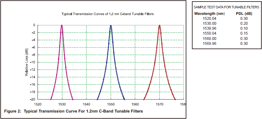
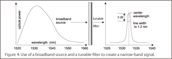
The typical output wavelength distribution is demonstrated in Figure 4.
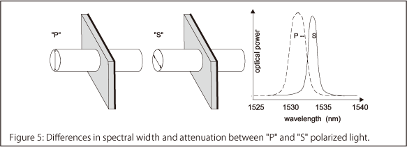
The main problem with typical tunable filters that has been solved by OZ Optics is their polarization sensitivity. As the angle of incidence increases, the sensitivity to polarized light also increases. (See Figure 5) This is a very important point in optical systems as the separation of the S and P polarizations causing large PDL can have detrimental affects on the system.
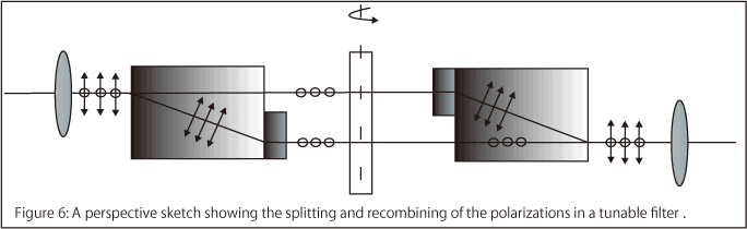
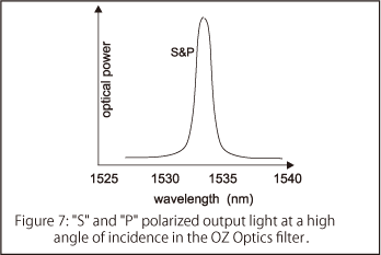
OZ Optics' tunable filters utilize an optical technique to control PDL making the spectral response polarization insensitive. The polarization insensitivity is accomplished through the precision alignment of optical components on both the input and output side of the filter. As demonstrated in Figure 6. below, the light is first split into its respective polarizations and then one of the polarizations is rotated such that the light incident on the filter is all the same polarization. After passing through the filter the other polarization is rotated and then the beams are combined for the final focusing and collection into the fiber. By rotating the light and having a common polarization pass through the filters the PDL effect of the filter at high angles of incidence is avoided.Therefore, the spectral response of S and P polarizations remain the same for increasing angles of incidence. See Figure 7.
技術資料
データシート
この製品に関するお問合せフォーム
フォームが表示されるまでしばらくお待ちください。
しばらくお待ちいただいてもフォームが表示されない場合、恐れ入りますが こちら までお問合せください。